

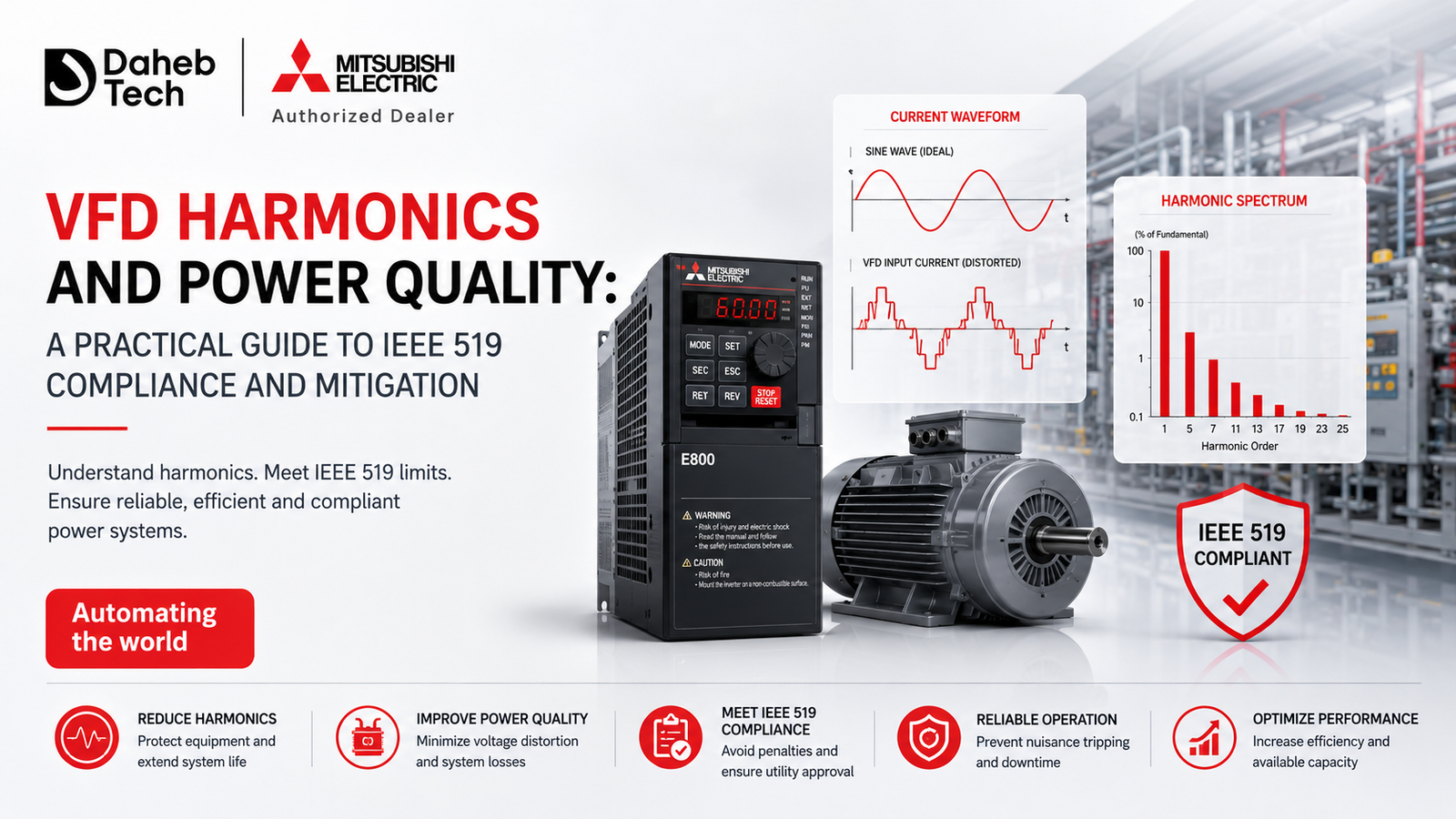
VFDs are non-linear loads their rectifier stage draws current in sharp pulses rather than a smooth sine wave, injecting harmonic currents back into the plant's power distribution system. Left unmanaged, this distorts voltage waveforms for every other piece of equipment sharing that supply, can overheat transformers and neutral conductors, and can fail IEEE 519 compliance checks required for utility interconnection or commissioning sign-off. Mitigation options range from a simple line reactor to full active front-end drives, and the right choice depends on how many VFDs are on the bus, their total load relative to system capacity, and how strict the applicable THD limit is.
As VFDs have become the default method for energy-efficient motor control across manufacturing, the harmonic distortion they introduce has shifted from a niche power-quality concern to a routine part of electrical system design. This guide explains why VFDs cause harmonics, what IEEE 519 actually requires, how to measure the problem correctly, and how to choose a mitigation strategy that fits the situation rather than over- or under-engineering the fix.
A VFD controls motor speed by first converting incoming AC power to DC, then using an inverter stage to synthesize a variable-frequency AC output. That front-end rectification is the source of the problem: a standard six-pulse rectifier draws current in narrow, non-sinusoidal pulses rather than following the smooth sine wave of the incoming supply. Those current pulses are rich in harmonic content additional current components at multiples of the fundamental frequency (the 5th, 7th, 11th, and 13th harmonics are typically the most significant in VFD applications).
Because a growing share of modern industrial and even commercial loads are non-linear (VFDs, UPS systems, LED drivers, switch-mode power supplies), harmonic distortion has become a much more common and cumulative problem across the whole electrical distribution system, not an isolated one-off.
Left unaddressed, harmonic distortion isn't just a compliance paperwork issue — it has real, measurable consequences:
IEEE 519 is the standard most commonly referenced for harmonic control in industrial power systems, and understanding its two core metrics is essential before specifying any mitigation equipment:
The standard sets its limits on a sliding scale: systems with a higher short-circuit ratio at the point of common coupling (larger, stiffer supplies relative to the load) are allowed more current distortion, while systems with a lower ratio are held to tighter limits, since they have less headroom to absorb distortion without affecting other equipment. Because the exact allowable percentage depends on this ratio and on the specific voltage class involved, the standard's own bracket tables should be checked against the actual system configuration — an engineer should confirm the applicable limit for the specific point of measurement rather than applying a single rule-of-thumb percentage across every project.
A common and costly mistake is selecting harmonic mitigation equipment based on a single, short measurement, or none at all. Harmonic current magnitude and frequency content from a VFD change with loading — a lightly loaded drive may show low-magnitude harmonics across many frequencies, while the same drive under heavy load can produce much more prominent distortion at specific harmonic orders. A single snapshot measurement can easily miss the worst-case condition entirely.
A more reliable approach:
Mitigation options range widely in cost, complexity, and effectiveness. The right choice depends on how many VFDs are involved, their combined size relative to the system's capacity, and how strict the applicable limit is.
|
|
|
|
|
|
|
|
|
|
|
|
|
|
|
|
|
|
|
|
|
|
|
|
|
|
|
|
|
|
As a general pattern: single-drive, moderate-load applications are often well served by reactors or a passive filter, while facilities running multiple large VFDs on a shared bus — where harmonic currents compound — increasingly justify multi-pulse or active front-end drives despite the higher upfront cost, since the compliance and equipment-protection risk scales with the combined load.
Do all VFDs cause the same amount of harmonic distortion? No. Standard six-pulse VFDs are the most common source of harmonic distortion, while multi-pulse and active front-end drives are specifically engineered to reduce harmonic generation at the source, often at a higher upfront cost.
Is a line reactor enough to meet IEEE 519 compliance? It depends on the system. Line reactors are a low-cost first step that reduces higher-order harmonics, but they have limited effect on the 5th and 7th harmonics, which are often the most significant contributors in VFD applications. Facilities with tighter compliance requirements or multiple VFDs on a shared bus often need additional mitigation beyond a reactor alone.
Does harmonic mitigation only matter for large industrial facilities? No, though the risk does scale with load size relative to system capacity. Even a single VFD on a facility with a relatively small electrical service can affect voltage THD as measured at the point of common coupling, since smaller systems generally have less capacity to absorb distortion.
How often should harmonic levels be re-measured after mitigation equipment is installed? At minimum, once after commissioning to confirm the mitigation is performing as specified, and again if additional VFDs or other non-linear loads are added to the same electrical system afterward, since combined harmonic loading changes with each addition.
Daheb Tech's technical team can help assess harmonic risk during your VFD and power distribution design, and recommend the right mitigation approach for your specific drive configuration — whether you're specifying a heavy-duty drive like the FR-A800, a higher-capacity FR-A840, or a fan/pump-focused FR-F840. Get in touch or explore our full product range.